Cross-Country Render Farm Architecture: WireGuard, BBR, and Shared SMB Cache Design
Overview
Introduction
Building a render farm that lives inside one rack, in one room, on one switch is a solved problem. Cable runs are short, round-trip times are measured in microseconds, and the asset library sits on a NAS that every worker reads at switch-port speed. Most render farm guides quietly assume this topology, because it is the one where everything just works.
The architecture changes when the farm has to span more than one site. A 20-node cluster split across two locations in the same metro is already a different network problem; a cluster that stretches across countries is a different problem again. Round-trip times stretch from sub-millisecond to tens or hundreds of milliseconds, jitter on public ISP routes becomes constant background noise, the MTU between any two endpoints becomes a question instead of an assumption, and the asset library that used to live on a single NAS has to either replicate to every site or be cached on demand. The naive approach — same NAS, same submission queue, same SMB share, just longer wires — surfaces as silent failure modes: sessions that connect but never transfer a frame, render submissions that hang at 99 percent because the final asset push to a remote node times out, license check-outs that succeed locally and fail remotely for no obvious reason.
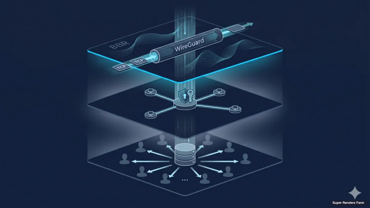
This article describes the architecture we run for cross-country render farm deployments — WireGuard hub-and-spoke topology, TCP BBR congestion control, MSS clamping discipline, a shared SMB3 cache layer, and a hardened firewall surface. The components are common, the configuration choices are not always obvious, and the lessons learned mostly cost us debugging time before they cost anyone money. The audience for this writeup is infrastructure architects and DevOps engineers who are sizing a similar build, plus IT decision-makers who want to know what their team is signing up for. For a step-by-step operational walkthrough of the same stack, our operational deployment guide covers the day-by-day rollout sequence. For a higher-level overview, the cross-country render farm overview page covers the business case.
WireGuard Hub-and-Spoke Topology

Encrypted tunnel linking two distant sites
The transport layer for the cluster is WireGuard. We use it both for client connections (artists' workstations connecting to the farm) and for the site-to-site link between the primary datacenter and the secondary location.
What artists actually run over that tunnel — the remote-desktop protocol streaming each workstation — is its own decision; our comparison of Moonlight, Parsec, and RDP for GPU rendering walks through the trade-offs. The topology is hub-and-spoke: one WireGuard server runs at the main datacenter gateway, every client peer connects in to that hub, and the secondary site connects as another peer with a routed subnet behind it.
WireGuard's appeal for this kind of build is mostly mechanical. The protocol uses fixed modern cryptography (Curve25519 for key exchange, ChaCha20-Poly1305 for the data plane, BLAKE2s for hashing), runs in the Linux kernel rather than in userspace, and configures with a key-and-allowedips file that fits on a single screen. Compared to OpenVPN, the configuration surface is roughly an order of magnitude smaller, the throughput on a typical Xeon node is several times higher at the same CPU cost, and the codebase is small enough that audit becomes tractable. Compared to IPsec, there is no IKE negotiation phase that can fail in interesting ways, no peer-identity dance during rekey, and no userspace daemon to crash. We have run all three across past deployments; the WireGuard configurations are the ones that stay up without intervention.
The hub-and-spoke layout means every site-to-site flow transits the main datacenter gateway. For a two-site cross-country deployment this is the right tradeoff: it concentrates the public-IP attack surface at one box, applies a single set of routing and firewall rules at one chokepoint, and makes monitoring straightforward because every handshake and flow counter is visible at the hub. A full mesh would shave one hop off site-to-site traffic but multiply the configuration work and public attack surface by the square of the site count. For two or three sites, hub-and-spoke wins on operational simplicity.
The hub listens on UDP port 51820 (the default), and that is the only port the public interface accepts. There is no TCP fallback. UDP-only is deliberate — WireGuard's congestion behavior is built around UDP datagrams, and a TCP-over-TCP tunnel reliably degrades long-distance throughput. On networks that block UDP entirely we treat that as a customer-side constraint and route around it at a different layer.
Each client peer is configured with a single AllowedIPs entry covering the cluster's internal subnet. The site-to-site peer has AllowedIPs covering the remote LAN subnet so the kernel knows which packets to encapsulate. PersistentKeepalive is set to 25 seconds on every peer behind NAT, which keeps the UDP conntrack entry alive between handshakes. We have skipped this exactly once and spent the next two days debugging "connection drops every 90 seconds on the secondary site"; on the third site, PersistentKeepalive was the first line of the config file.
TCP BBR Congestion Control
Once the WireGuard tunnel is up, the next layer is TCP behavior. Linux ships with CUBIC as the default congestion control algorithm. CUBIC scales its congestion window on a cubic curve as a function of time since the last loss event, which works well on links where packet loss is a reliable signal of congestion. The catch is the phrase "reliable signal." On long-distance public ISP routes, packet loss is often not congestion at all — it is queue overflow on an intermediate router, a wireless link doing retransmits invisibly to TCP, a misconfigured rate-limiter, or a routing transient. CUBIC treats all of these as congestion and collapses the window even when the bottleneck has plenty of capacity left.
BBR (Bottleneck Bandwidth and Round-trip propagation time) is the alternative we use on cross-country links. BBR ignores packet loss as the primary congestion signal and instead measures the path's bottleneck bandwidth and minimum round-trip time directly. It then paces the sender at the bottleneck rate, with a window sized to keep one bandwidth-delay product of data in flight. On a long fat network — high bandwidth, high RTT, modest random loss — BBR keeps the pipe full where CUBIC would repeatedly halve its window for non-congestive losses.
The practical effect on a render farm is measurable. Asset transfers over a cross-country tunnel, on the same hardware, move from spiky throughput with frequent stalls under CUBIC to a smoother throughput curve closer to the path's actual capacity under BBR. Headline numbers vary by ISP route and time of day, but switching the cluster sender side to BBR has consistently produced higher steady-state throughput and shorter tail latencies on the routes we operate.
We use the BBR implementation that has been in the mainline Linux kernel since version 4.9, enabled with a one-line sysctl: net.core.default_qdisc=fq plus net.ipv4.tcp_congestion_control=bbr. Both lines go in /etc/sysctl.d/99-bbr.conf and survive reboot. The mainline kernel BBR is the version we have run in production for years. Newer research branches of the algorithm exist but introduce behavior changes we have not had time to validate on our specific ISP paths; the upgrade path is a separate roadmap item.
BBR is set on the sender side of any large flow — the cache box and the render manager for asset transfers, the receiver side for any reverse-direction flow like license callbacks and log shipping. BBR on one end is enough to see most of the benefit; BBR on both ends helps a little more on bidirectional flows.
TCP MSS Clamping
Of all the network problems that show up after the WireGuard tunnel comes up, the one that has cost us the most debugging time is MTU. The symptom is consistent and confusing: small packets pass cleanly (ping works at default size, SSH echoes characters, the WireGuard handshake completes), but large packets disappear into the tunnel and never come out. TLS handshakes hang halfway through. SMB sessions connect but fail on the first large read. RDP sessions establish, show the login screen, then freeze when the user types anything that triggers a screen update. License servers check out for small tokens and time out for large ones.
The cause is the WireGuard tunnel's encapsulation overhead reducing the effective MTU below the path MTU that endpoints negotiate based on their LAN interfaces. WireGuard adds 60 bytes (20 IPv4 + 8 UDP + 32 WireGuard) to every packet. A 1500-byte payload on the LAN side becomes a 1560-byte packet on the public side, fragmented or dropped depending on the path. Path MTU Discovery (PMTUD) is supposed to fix this with ICMP "Fragmentation Needed" replies, but PMTUD breaks on the modern internet routinely — ICMP is often filtered upstream of the sender, the "use smaller packets" signal never arrives, and the tunnel silently drops large packets.
The fix is TCP MSS (Maximum Segment Size) clamping. We configure the router-side WireGuard interface to rewrite the MSS option in every TCP SYN traversing the tunnel, capping it at the tunnel's effective MTU minus TCP/IP overhead. With a tunnel MTU of 1420 bytes (a safe choice that survives most upstream variations), the MSS clamp is 1380. Any TCP connection after the rule is in place negotiates a 1380-byte MSS, the sender emits 1420-byte packets that fit cleanly, and the silent drops stop.
The clamp goes on the FORWARD chain of the router-mode WireGuard host, on the wg0 interface, applied to TCP handshake packets. The iptables idiom is iptables -t mangle -A FORWARD -o wg0 -p tcp --tcp-flags SYN,RST SYN -j TCPMSS --clamp-mss-to-pmtu (or --set-mss 1380 for a fixed value). nftables has the equivalent. The rule needs to apply in both directions if both sides originate TCP connections, which on a render farm is the common case.
There is no way to feel the MSS clamp is missing until something large fails — small workloads test fine. The clamp is one of those configurations that costs nothing when applied correctly and produces hours of confused debugging when omitted. We put it in the standard deployment checklist after the first time a 6 a.m. support ticket about "SMB transfers hanging at random sizes" resolved at 8 a.m. with a one-line iptables rule.
Shared SMB3 Cache Design

Shared cache serving assets locally to render workers
Render workloads are asset-heavy and read-dominated. A typical scene runs from a few hundred megabytes to several tens of gigabytes — geometry, textures, simulation caches, and the rendering DCC's project files. Across a 20-node cluster the same scene needs to be readable by every worker that picks up a frame. The naive approach is to copy the scene to every node before the render starts. With a 10 GB scene and 20 nodes, that moves 200 GB across the network for a 10 GB working set. Multiply by tens of scenes per day per studio and the duplication cost dominates the build.
The architecture we use instead is a single shared cache layer per site, exposed to render workers over SMB3. The cache is one Ubuntu 22.04 LTS box with a single SSD (NVMe class), formatted ext4, with the cache directory exposed by Samba via SMB3. Each render worker mounts the SMB share on boot through cifs-utils and reads asset files as if they were local. The first worker to need a given asset triggers a pull from the upstream cloud asset store into the cache; subsequent workers and subsequent frames read from the LAN cache at switch-port speed. Per-site, the cache box sits one switch hop from every worker; the asset reaches the cluster once and serves twenty workers.
A few design choices deserve unpacking. The cache is a single SSD, not a RAID array, because the cache is by definition rebuildable from the upstream cloud asset store. If the SSD fails, the worst case is a delay while the next asset request pulls from cloud, plus a rebuild of any in-flight render that depended on a non-cached intermediate file. We mitigate the "in-flight render" risk by rsyncing finished render outputs from the cache to a NAS at the end of each job, so an SSD failure does not lose any deliverable that has already shipped. Skipping RAID saves the hardware cost, the controller complexity, and the write-amplification overhead that some RAID levels impose on SSDs.
The file system is ext4 rather than ZFS or btrfs. We have used both ZFS and btrfs in past builds, and the feature sets they bring (snapshots, checksumming, compression) are real benefits in some workflows. For a render cache, the read pattern is mostly sequential and bandwidth-bound rather than transaction-heavy, and the cache contents are by design discardable. Ext4 keeps the storage stack simple and removes a class of failure modes from the incident postmortem set. Operators who already run ZFS at scale can absolutely use it here, but for a deployment where cache-layer simplicity outweighs individual feature wins, ext4 is the choice.
The pre-warm strategy matters. Before a deadline-driven job starts, the artist or pipeline TD pushes the scene's assets into the cache through a pre-staging tool. The first frame that lands on a worker then reads from a warm cache rather than waiting on a cold pull. The pre-warm step is optional for jobs that run overnight (cold pull is fine), and important for jobs that need to complete in a constrained window.
Cross-site cache sharing works through the WireGuard site-to-site tunnel. The secondary site has its own cache box and workers, but its cache can also reach the primary site's cache over the tunnel for any asset warm there and not yet warm locally. In practice we configure the secondary site's cache to fall back to the primary cache for misses before going to upstream cloud — keeping inter-site traffic on the encrypted tunnel and avoiding cloud egress charges for assets that already live inside the farm. This is one of the practical benefits of the MSS clamp being correct: large asset transfers between sites move at tunnel-saturating throughput rather than stalling at the small-packet ceiling.
Internal Services: DNS and NTP
A cluster needs to know its own hostnames. The naive choice is to put every host in /etc/hosts on every node, which works for two nodes and starts failing at twenty. The correct choice is internal DNS, and we run dnsmasq on the same gateway box that runs WireGuard. The cluster lives in a .lan zone — cache.lan, rn-a01.lan through rn-a20.lan, mgr.lan, nas.lan. Each name resolves to the corresponding internal IP on the cluster subnet, and each worker's /etc/resolv.conf points at the dnsmasq server.
The benefit is that any IP reassignment, host swap, or topology change requires updating one configuration file (the dnsmasq hosts file) rather than touching every node. The benefit also extends across the site-to-site tunnel: a worker at the secondary site can resolve cache.lan to the secondary cache through its local dnsmasq, and can resolve mgr.lan to the primary site's render manager through DNS forwarding across the tunnel. We have, in the past, used IP literals in render manager configurations and regretted it every time a node moved.
The dnsmasq gotcha that has bitten us — and bitten enough operators that it deserves its own paragraph — is the interface= line. dnsmasq, by default, listens on every interface, which seems fine until you realize that the gateway box has at least three: the public-facing WAN, the internal LAN, and the WireGuard tunnel wg0. If you set interface=eth1 thinking you are restricting dnsmasq to LAN only, you have just made the WireGuard-connected secondary site unable to resolve any .lan name, because wg0 is not listed. The correct line is interface=eth1,wg0 (or the equivalent for your interface names), or an except-interface= line that names only the WAN. We have seen this misconfiguration produce the "remote site can ping the cache by IP but cannot SMB-mount it by hostname" symptom more than once.
NTP is the other internal service. We run chrony on the gateway as an NTP server, with the gateway itself synced to public NTP pools and every node syncing to the gateway. The motivation is render manager log correlation: if a frame fails, the render manager's log entry and the worker's log entry need to share a timeline within milliseconds. Clock drift on a 20-node cluster, especially when nodes have been up for weeks, becomes a real source of "this log entry doesn't seem to match" debugging confusion. chrony keeps drift under a few milliseconds and removes that class of confusion.
Firewall: ufw with Default-Deny Inbound
The gateway sits on the public internet, and its firewall posture is "default-deny inbound, default-allow outbound, default-allow forward for tunneled traffic." On Ubuntu 22.04 LTS, the tool we use to manage this is ufw — the Uncomplicated Firewall. ufw is a frontend over nftables (or iptables on older systems) that exposes a small command surface and refuses to do anything surprising. For a gateway box where the firewall config is the difference between "secure" and "compromised within hours," a small command surface is a feature.
The configured public surface is one rule: ufw allow 51820/udp comment 'wireguard'. Nothing else inbound. SSH from the public side is closed; we administer the gateway through the WireGuard tunnel from a known operator IP. SMB, DNS, NTP, and HTTPS (for the render manager UI) are all on internal interfaces only. The ufw default deny incoming and ufw default allow outgoing settings cover the rest of the surface.
The forward chain needs care. The gateway is acting as a router for cluster traffic between wg0 and the internal LAN, and the default ufw posture is to deny forward. We set DEFAULT_FORWARD_POLICY="ACCEPT" in /etc/default/ufw and then narrow the forward rules to specific source/destination pairs in the FORWARD chain. The combination — default-deny incoming, default-deny forward at boot, then explicit forward ACCEPTs between known cluster subnets — gives a posture that is auditable and that does not accidentally route traffic between sites that should not be talking.
Per-node host firewalls extend this Tier-1 gateway layer into a Tier-2 host layer. Each render node runs ufw locally with rules that allow only the cluster's render manager and the cache box to initiate connections. A compromised worker cannot pivot to another worker without first defeating the host firewall, and the gateway logs every unexpected forward attempt. The two-tier model — gateway Tier 1, per-host Tier 2 — is the same any reasonable on-prem cluster runs; what changes on a cross-country deployment is that the Tier 1 surface now defends against the public internet. The gateway is the perimeter; per-host firewalls are defense-in-depth.
Architecture Diagram

Hub-and-spoke render-farm topology, single secure tunnel to internet
The text description above maps to the following ASCII diagram, which is the same one we draw on a whiteboard during deployment kick-offs:
                          PUBLIC INTERNET
                                 |
                                 | UDP 51820 (only port open)
                                 v
        +------------------------+------------------------+
        |               MAIN DATACENTER                   |
        |                                                 |
        |   +----------------+        +---------------+   |
        |   |    Gateway     |--LAN-->|  Render Mgr   |   |
        |   |  (ufw + wg0 +  |        |    (mgr.lan)  |   |
        |   |  dnsmasq +     |        +---------------+   |
        |   |  chrony + BBR) |                            |
        |   +-------+--------+        +---------------+   |
        |           |              -->|    Cache      |   |
        |           |              |  |  (cache.lan)  |   |
        |           v              |  |  SSD ext4 SMB3|   |
        |   +----------------+     |  +-------+-------+   |
        |   |  Worker Subnet |<----+          |           |
        |   |  rn-a01..a20   |                v           |
        |   |  (Tier-2 ufw)  |       +---------------+    |
        |   +----------------+       |    NAS        |    |
        |                            |   (archive)   |    |
        |                            +---------------+    |
        +------------------+------------------------------+
                           | WireGuard site-to-site
                           | (BBR + MSS clamp)
                           v
        +------------------+------------------------------+
        |              SECONDARY SITE                     |
        |                                                 |
        |   +----------------+      +-----------------+   |
        |   |  Site Gateway  |----->|  Local Cache    |   |
        |   |  (wg0 spoke)   |      |  (falls back    |   |
        |   +-------+--------+      |   to primary)   |   |
        |           |               +--------+--------+   |
        |           v                        |            |
        |   +----------------+               v            |
        |   |  Worker Subnet |       (renders run         |
        |   |  rn-b01..b08   |        locally; outputs    |
        |   |  (Tier-2 ufw)  |        ship over tunnel)   |
        |   +----------------+                            |
        +-------------------------------------------------+
The diagram is intentionally generic — no specific city pair, no specific ISP, no specific subnet numbering. Every site we deploy follows the same shape; the numbers vary.
Performance Characteristics
Throughput numbers depend on the ISP route and the time of day, but the shape of the performance is consistent across the deployments we have run. On a tunnel between two sites in the same metro (sub-10 ms RTT), large transfers move at near-line-rate on the bottleneck link, and a render worker reading from cache feels indistinguishable from a worker reading from a local disk. On a tunnel between sites in different countries (50–150 ms RTT depending on the route), large transfers settle into a steady BBR-paced throughput close to the bottleneck bandwidth, with the MSS clamp keeping per-segment size matched to the tunnel MTU.
The local-LAN cache read is where the architecture earns its keep. A render worker reading a 4 GB texture pack from cache.lan over SMB3 on a switched gigabit LAN finishes in roughly the time the switch port takes to push the bytes — tens of seconds rather than the multi-minute timeframes a cold pull from cross-country cloud storage would take. For a job that touches the same texture pack across two hundred frames, cache hit ratio approaches 1.0 after the first warm read, and the cross-country tunnel is used only for the original pre-warm, cross-site sync of secondary-site outputs, and steady-state telemetry.
For 4K and 8K render frames specifically, the architecture's value scales with frame size. An 8K EXR sequence with multiple AOVs can push individual frame outputs into the hundreds of megabytes, and 200 of them is a multi-tens-of-gigabytes write per scene. Keeping that write local-LAN and shipping only the final compressed output across the tunnel is the difference between "finishes overnight" and "finishes when the upload completes, sometime tomorrow."
Frequently Asked Questions
Q: Why WireGuard and not OpenVPN? A: WireGuard's configuration surface is smaller, its data-plane throughput is consistently higher on the same hardware, its kernel implementation removes a userspace failure mode, and its fixed-cipher posture removes a class of negotiation bugs. OpenVPN is a fine tool with twenty years of operational history; we use WireGuard because the operational properties for a long-running cluster tunnel are better on the metrics we care about (throughput stability, configuration auditability, kernel-level performance). On routes where WireGuard's UDP is blocked entirely, OpenVPN over TCP 443 is a legitimate fallback — but TCP-over-TCP introduces its own pathologies, and we treat that as a customer-side constraint rather than a default architecture.
Q: How does BBR help on noisy ISP routes? A: BBR uses bottleneck bandwidth and RTT as its congestion signal rather than packet loss. On routes where loss is dominated by buffer overflow at intermediate routers, wireless retransmits, or transient routing events — that is, most public ISP routes — BBR keeps the sender's pace matched to the path's actual bandwidth instead of repeatedly halving the window for losses that are not congestive. The effect is higher steady-state throughput, shorter tail latency on large transfers, and fewer "the transfer stalled for thirty seconds and then resumed" incidents on long flows.
Q: What is MSS clamping and why do I need it? A: MSS clamping rewrites the Maximum Segment Size option in TCP SYN packets so that the negotiated segment size fits cleanly through a tunnel with reduced effective MTU. Without it, endpoints negotiate a segment size based on their LAN interfaces (typically 1500-byte MTU, 1460-byte MSS), the WireGuard tunnel cannot carry those packets at full size, Path MTU Discovery fails because ICMP is filtered somewhere upstream, and large packets disappear silently. The symptom is "small packets work, large packets do not" — pings succeed, TLS handshakes hang, SMB transfers stall mid-file. The fix is a one-line iptables or nftables rule on the router-side WireGuard interface.
Q: Can I deploy this architecture myself, or do I need a render farm vendor?
A: The architecture is built entirely from open-source components — WireGuard, Linux's BBR implementation, iptables/nftables, Samba SMB3, dnsmasq, chrony, ufw, ext4. There is no SRF-only component. A team with infrastructure-engineer skills can deploy the same stack themselves, and the configuration choices in this article are not secrets; they are the choices we made because they worked. What a vendor brings to the table is the operational experience — the gotchas like dnsmasq's interface= line, the MSS clamp discovery story, the right-sizing of the cache SSD, the pre-warm tooling — rolled into a deployment playbook that does not require rediscovery on every build. Whether a team wants to absorb that experience curve or buy past it is a budget and timeline question, not a technical one.
Q: What is the cache hit ratio for typical render workflows? A: For frame-parallel workloads where the same scene is rendered across many frames (the dominant pattern in animation, VFX, archviz, and product visualization), the cache hit ratio approaches 1.0 after the first warm pull of each asset. The cold-pull penalty is paid once per asset per cache, and every subsequent worker on the same site reads from the warm cache at LAN speed. For workloads that touch a different asset set per frame (rare, but it happens in some procedural workflows), the cache hit ratio is lower and the cache acts more like a transit buffer than a long-term store. The pre-warm step before deadline-driven jobs effectively makes the cache hit ratio 1.0 for the planned workload.
Q: How does this architecture scale beyond 20 nodes? A: The hub-and-spoke WireGuard topology scales linearly with peer count — the hub's CPU cost is per-peer crypto and per-packet routing, and a modern Xeon gateway can handle hundreds of peers before becoming the bottleneck. The cache layer scales by either growing the single cache box (more SSD capacity, faster NIC) or by sharding across multiple boxes with a workload-aware mount strategy. For builds beyond 50 nodes per site, we typically add a second cache box and split workers between them; beyond 100 nodes per site, the cache layer becomes a distributed read-replica design, and that is a different article. The cross-country tunnel itself does not need an architectural change as the cluster grows — BBR pacing and MSS clamp continue to do their jobs at any aggregate flow rate, as long as the underlying ISP link has the capacity.
For more practical detail on the deployment sequence we follow to bring this architecture up, see our operational deployment guide. For the security posture overlaid on top of this network design, our network segmentation security article covers the Tier-1 and Tier-2 firewall model in more depth. And for the field-tested edge cases we did not always get right the first time, the deployment lessons learned writeup covers the specific failure modes that shaped this architecture.
About Thierry Marc
3D Rendering Expert with over 10 years of experience in the industry. Specialized in Maya, Arnold, and high-end technical workflows for film and advertising.


