How to Deploy a 20-Node Dedicated GPU Render Farm Across Country Borders (2026)
Overview
Introduction
When a creative team asks for a dedicated render farm spanning multiple countries, they are usually working around a constraint a SaaS render farm cannot solve. They might be a studio that contractually cannot let a third party hold their credentials, a distributed team where artists in one country drive nodes in another, or a production house whose multi-month engagement makes per-frame metering economically wrong.
Running a cluster like this hands-off depends on a solid unattended pipeline; our headless render farm unattended workflow guide covers that operational layer.
In our experience, the hard part is rarely "rent more GPUs." It is connecting the right pieces: customer-owned cloud storage, a private GPU fleet sized to the workload, encrypted cross-border transport that survives jitter, and a remote-desktop layer that does not collapse on a heavy 3D viewport. When one piece is wrong, the cluster runs, but artists notice — and the engagement quietly degrades.
We operate Super Renders Farm, a cloud render farm with a substantial CPU + GPU fleet, and also stand up dedicated GPU clusters for teams whose workflows do not map onto our managed service. This article is a field guide from those deployments — how we architect a 20-node dedicated GPU render farm serving a distributed creative team of artists across borders from a single dedicated facility, with honest notes on the choices we made, the choices we walked back, and the lessons we now apply by default. If you are weighing dedicated infrastructure against our managed render farm rental, this guide will help you decide whether the dedicated path is worth the architectural surface area.
Dedicated vs SaaS Decision Criteria
Most rendering workloads do not need a dedicated cluster. A managed cloud render farm submits a scene, schedules the frames, and bills per minute. There is no infrastructure to own, no firewall to maintain, and no operational team to assign on the customer side. For project-based work — a single short, a 30-second commercial, a batch of stills — that model wins on every axis that matters.
A dedicated cluster only earns its complexity when one or more of the following are true:
- IP control is contractual, not preferential. The customer's master service agreement or end-client contract forbids a third party from holding scene files or render credentials. SaaS pipelines that mediate scene upload break this constraint even if the underlying compute is identical.
- The engagement runs for months, not days. Fixed-shape work — a long-running animated series, a multi-quarter archviz pipeline, an ongoing virtual production stage — pays back the up-front architecture cost. Per-frame metering, by contrast, multiplies linearly with duration and stops being competitive past a certain runway.
- The workflow is custom enough that a managed pipeline cannot host it. Custom DCC plugin stacks, in-house render managers, simulation-heavy pipelines that pre-bake to a shared cache, or proprietary tooling chains all push toward dedicated nodes that the customer can configure directly.
- Bring-your-own-cloud is a hard requirement. When the customer's project assets live in a cloud file-streaming platform under the customer's account, the cluster must sign in as the customer, not as the infrastructure provider. This is the "Model B" pattern discussed in detail below.
- Network segmentation needs go beyond per-tenant VLAN. Some workflows need the cluster to be invisible to the provider's broader network — not just isolated logically, but isolated by route as well.
If none of these criteria apply, a managed render farm is the right choice. If two or more apply, the conversation shifts toward dedicated.
For a full side-by-side of those two models — the multi-tenant SaaS pool versus a single-tenant dedicated cluster — across economics and security, see our SaaS render farm vs dedicated cluster comparison. The remaining question is geographic: do the artists driving the work sit close to the facility, or does the cluster need to serve them across a public ISP backbone that crosses national borders?
Architecture Overview
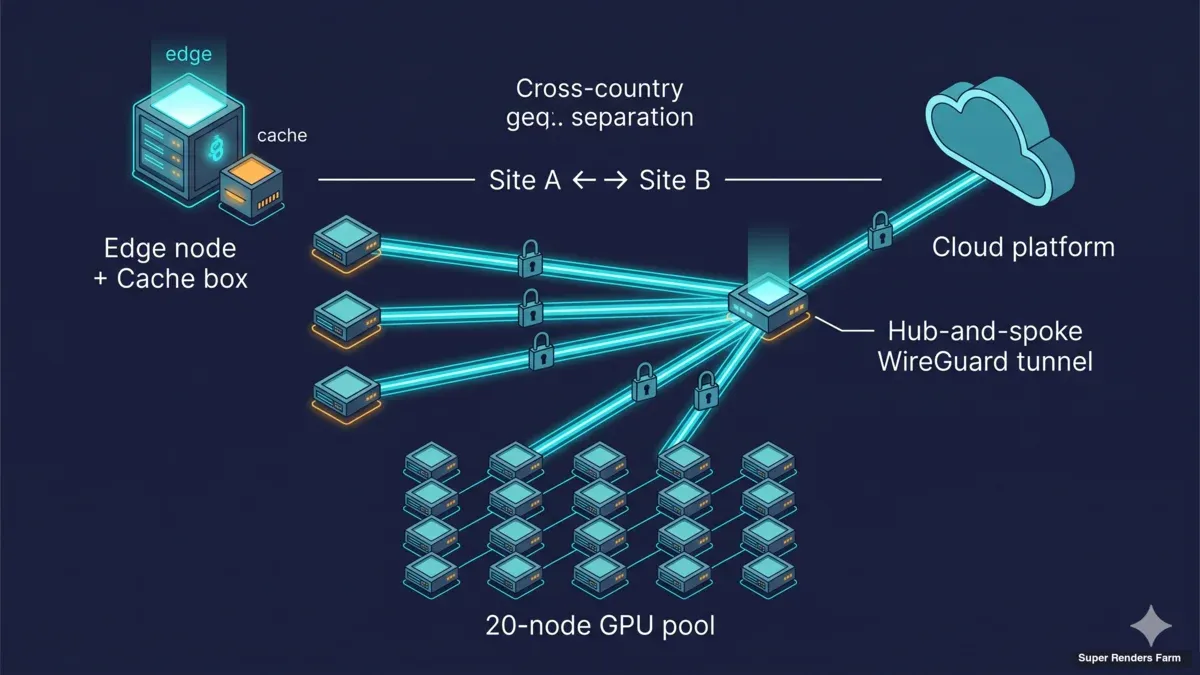
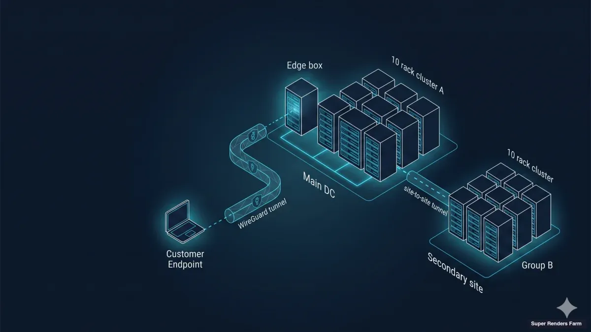
Network topology diagram showing WireGuard hub-and-spoke architecture with cross-country geographic separation 20-node GPU pool and cloud platform connectivity
The architecture we deploy for cross-country dedicated clusters has three planes: a transport plane, a compute plane, and a storage-acceleration plane. Each plane has a single failure-mode that, in our experience, accounts for most of the operational pain when it breaks.
        [ Remote artists — distributed across countries ]
                          │
                          │  WireGuard hub-and-spoke
                          │  (UDP 51820, encrypted end-to-end,
                          │   BBR + MSS-clamped transport)
                          ▼
   ┌─────────────────────────────────────────────────────┐
   │   Super Renders Farm — dedicated cluster facility    │
   │                                                       │
   │   ┌─────────────────────────────────────────────┐   │
   │   │  EDGE + CACHE BOX (single Ubuntu host)       │   │
   │   │   • WireGuard hub (NAT/MASQUERADE)           │   │
   │   │   • Samba SMB3 cache (single SSD, ext4)      │   │
   │   │   • dnsmasq (.lan zone)                      │   │
   │   │   • chrony (NTP)                             │   │
   │   │   • ufw + BBR + TCP MSS clamp                │   │
   │   └────────────────────┬────────────────────────┘   │
   │                        │ LAN                          │
   │   ┌────────────────────▼────────────────────────┐   │
   │   │   20 × RTX 5090 render nodes                 │   │
   │   │   (Windows 11 Pro, Sunshine, cloud file-     │   │
   │   │    stream client, cache mount — uniform      │   │
   │   │    image across the fleet)                   │   │
   │   └─────────────────────────────────────────────┘   │
   └─────────────────────────────────────────────────────┘
                              │
                              ▼
    [ Customer's cloud file-streaming platform —
      customer signs in on each node; Super Renders
      Farm does not hold credentials (Model B) ]
The transport plane is WireGuard, in a hub-and-spoke pattern. Every artist's workstation connects to the hub at the cluster facility through an encrypted UDP tunnel; all artist-to-cluster traffic, regardless of which country the artist sits in, traverses the same tunnel topology. The compute plane is twenty Windows 11 Pro nodes, each driving a single NVIDIA RTX 5090 with 32 GB of VRAM, deployed as a single uniform pool in one facility. The storage-acceleration plane is a single edge-and-cache box at the facility that hosts a Samba SMB3 share backed by a single SSD on ext4 — together with the network services the cluster depends on (DNS, NTP, firewall).
We break down each of these three planes (the WireGuard transport, the uniform GPU pool, and the SMB3 cache box) in our cross-country render farm architecture guide.
A key design decision: the edge box and the cache box are the same machine. An earlier version of this architecture put the edge gateway on a separate appliance and the cache on a NAS, which created race conditions during cold pulls and two surfaces to patch. Consolidating onto one Ubuntu 22.04 LTS host removed both problems. The box becomes a critical resource — but customer project data still lives in the cloud file-streaming platform, so the cache re-warms from upstream after any local failure.
20-Node GPU Cluster Setup
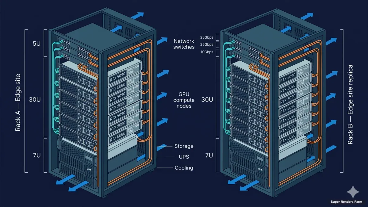
20-node GPU server rack elevation diagram showing RTX 5090 specifications cooling layout and cable management for cross-country deployment
The default sizing for the deployments we are describing is twenty RTX 5090 nodes, deployed as a single uniform pool inside one facility. This is the size that consistently maps well to a creative team in the ten-to-twenty artist range, which is the band where dedicated clusters earn out for IP-sensitive workflows.
Each node is the same hardware shape: a single RTX 5090 with 32 GB of VRAM, a modern multi-core CPU, 64 GB or 128 GB of system RAM, and an NVMe local disk sized for OS and scratch only. Persistent project data lives on the shared cache or in the upstream cloud file-streaming platform, never on the node itself.
The operating system on each node is Windows 11 Pro, deployed from a clean image. We deliberately do not pre-load DCC plugin stacks on the node image. The customer drives the install of their own DCC tools — Cinema 4D, Redshift, Houdini, After Effects, Blender, and others — so that the node image stays minimal and reproducible. When the engagement ends, we wipe and reimage from the same clean baseline.
We chose 32 GB of VRAM per node deliberately. Modern GPU renderers — Redshift, Octane, Arnold GPU, Cycles — increasingly load large textured scenes that simply will not fit in 24 GB cards. RTX 5090 at 32 GB is the current sweet spot for production renderers; it handles most archviz, motion design, and animation work without paging to system RAM, which is where mixed GPU pools quietly become slow.
The twenty nodes are configured identically — same image, same DCC install set, same cache mount, same WireGuard route — and present as a single pool to the customer's render manager. Deadline, Royal Render, or the customer's own scheduler treats the fleet as one resource without any per-group routing or manual rebalancing logic. Frames hand off to whichever node is free; the customer's render manager handles load distribution at the job-queue layer.
The fleet is layer-3 routable — the customer installs their own render manager and submits from a remote workstation rather than driving each node through remote desktop. This matters more than people expect: it is the difference between a cluster artists fight with and a cluster artists forget about.
Customer-Owned Credentials (Model B)
The single architectural decision that most often makes a dedicated cluster the right answer for IP-sensitive workflows is what we call Model B: customer-owned credentials. In Model A — the default for managed render farms, including our own SaaS service — the infrastructure provider holds credentials to the rendering pipeline. The customer uploads scene files; the provider's pipeline mediates the render. This works for the vast majority of workloads and is the model behind almost every commercial cloud render farm.
In Model B, the infrastructure provider supplies hardware, the operating system, the network, and the cache layer, but never holds the customer's authentication material for the cloud file-streaming platform or for the project's source data. The customer signs in to the cloud platform on each node, exactly as if they were sitting at their own workstation. Project files stream from the customer's cloud. Renders write back to the customer's cloud. The provider's role is bounded at the hardware-and-pipeline layer.
This matters for three reasons:
- Contractual: When the customer's downstream client has an NDA or master service agreement that restricts where credentials and source files can be held, Model B keeps the provider out of the scope of those restrictions. The customer does not need to negotiate the rendering provider into a contractual chain that was not designed for it.
- Audit: When the customer needs to demonstrate to a security auditor that their rendering pipeline does not expose credentials to a third party, Model B gives them a clean answer. The provider can produce hardware, network, and operational documentation; the customer produces the credential chain.
- End-of-engagement closure: Because the provider never held credentials, end-of-engagement cleanup is simpler. The customer revokes their own cloud sessions; the provider wipes the cache, reimages the nodes, and provides a written attestation that the cache and node images have been destroyed. There is no credential rotation step for the provider to certify because no credentials were ever held.
Model B is not for everyone. It puts the customer's operations team on the hook for credential lifecycle on every node — twenty rotations to coordinate if secrets rotate monthly. Teams with that operations practice already in place find the trade-off acceptable. Teams without it tend to stay on Model A managed rendering.
Cloud File-Streaming Integration
In the configurations we are discussing, the customer's project assets live in a cloud file-streaming platform — a service that exposes their cloud-backed project tree as a virtual filesystem on each node. The artist mounts the project; the node reads files on demand; the platform handles backing storage, versioning, and cross-region replication.
We integrate with a generic cloud file-streaming platform of the customer's choice. The platform sees a sign-in event from each node using the customer's account; the platform's client running on the node mounts the project tree at a known path; the customer's DCC application opens files from that path exactly as it would on a local workstation. The cloud platform does not need to be aware that the node is part of a render cluster.
What changes when this is wired into a 20-node cluster is the access pattern. A single artist on a single workstation pulls one project file at a time, on demand, while they work. Twenty render nodes opening the same scene at once for a frame range create a synchronized burst of cloud reads for the same assets. Without a cache, every node pulls every texture, every cached simulation, every dependency file, in parallel — which is both wasteful of international bandwidth and slow on the first frame of every range.
This is why the shared cache exists. We talk about it in detail in the next section, but the integration with cloud file-streaming is the reason it has to exist. Asset pulls from the cloud are concentrated through the cache box once, then distributed to all twenty nodes over the LAN. The cloud platform never sees twenty simultaneous fetches of the same texture — it sees one fetch, plus warm SMB reads inside our network.
The other practical detail is write-back. When a render frame finishes, the node writes output to the cloud file-streaming platform — back through the customer's account. The customer's team in the remote office sees the frames appear in the project tree in real time. There is no manual upload step, no provider-mediated transfer; the cloud platform handles the round trip.
Shared Cache Architecture
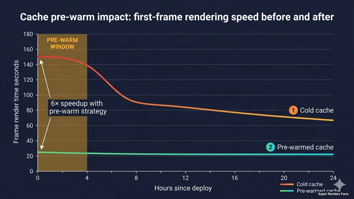
Timeline graph comparing first-frame rendering speed during cold cache versus warm cache phases with pre-warm window highlighted
The shared cache is one of two or three architectural choices that, when made wrong, will silently corrode a cluster's value. We have made it wrong in earlier deployments. The pattern that has held up over multiple builds is deliberately conservative.
A single edge-and-cache box runs Ubuntu 22.04 LTS, with a single 8 TB SATA SSD formatted as ext4 and exposed to the cluster over Samba SMB3. The cache mount appears on every render node at a fixed path (for example \\cache.lan\proj). When a node opens a project file through the cloud file-streaming client, the file streams through the local cache; subsequent reads of the same file on any node hit the SSD directly over the LAN.
There are three deliberate choices buried in that paragraph.
First, a single cache, not per-node caches. An earlier version of this architecture stored cache material per node. With twenty 5090 nodes, that meant up to 200 TB of redundant storage to manage, and twenty separate cache states to debug when something diverged. Consolidating to one shared cache cuts the storage footprint by a factor of twenty and makes the cache state a single artifact that the operations team can introspect.
Second, a single SSD on ext4, not RAID 10 with LUKS over XFS. The earlier plan called for the cache to live on a RAID 10 array with LUKS at-rest encryption on XFS. That plan was over-engineered for the actual hardware we deploy onto — one SSD, one filesystem, one mount. We removed the RAID layer, removed LUKS, and used ext4 because the cache is not the source of truth for project data. The customer's cloud is the source of truth. If the cache drive fails, we replace it and re-warm from upstream; we do not need redundancy at the cache layer because we have redundancy at the cloud layer. (At-rest encryption was outside the scope of this deal but is available as a separate engagement when a downstream client requires it.)
Third, pre-warm the cache before the first render day. This is the lesson we learned the hard way. On D-Day, every cache miss is the most expensive read in the cluster — it traverses the international link, pulls from the customer's cloud, and writes to local SSD before the renderer can consume it. Pre-warming, which is a structured walk through the project's asset tree the day before production starts, converts D-Day reads from cold cloud pulls into warm SMB reads. We now plan a pre-warm window into every dedicated cluster engagement.
Inside the facility, every node mounts the cache at the same fixed path (\\cache.lan\proj) over SMB3 on the local LAN. Because intra-facility traffic does not traverse the WireGuard tunnel, MSS clamping does not apply here and the link runs at gigabit Ethernet speeds end-to-end. The cache mount path is identical on every node, which simplifies the customer's render manager configuration — the same scene file path resolves the same way on every member of the pool.
Cross-Country Network Optimization
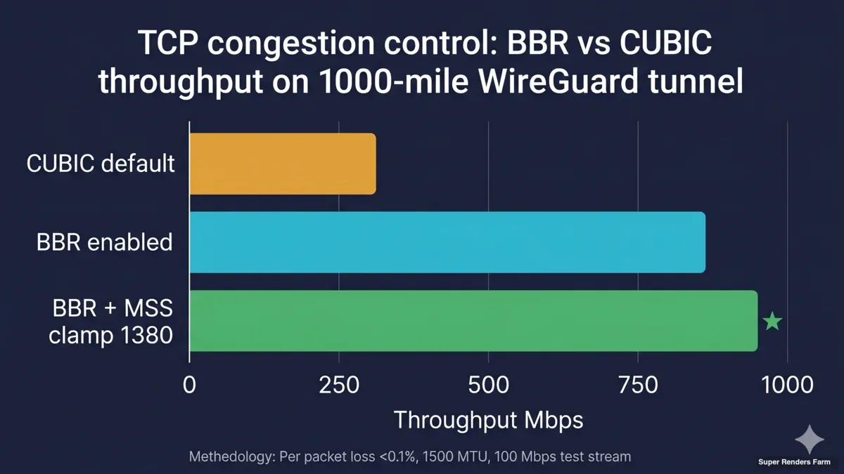
Bar chart comparing BBR versus CUBIC TCP congestion control throughput performance on cross-country render farm tunnel with MSS clamping impact
The transport layer is where a cross-country cluster either feels seamless or feels broken. The default behaviors of TCP/IP, IP-fragmentation, and DNS-over-VPN are subtly wrong for long-distance encrypted tunnels carrying SMB and remote desktop. Tuning the kernel and the network configuration is not optional; it is the difference between a working cluster and one that mysteriously drops large packets.
WireGuard, hub-and-spoke. Every artist connects from their workstation through a WireGuard client to the hub at the cluster facility. All traffic between the artist and the cluster is encrypted end-to-end. We deliberately use one VPN technology rather than mixing protocols; combining IPSec for one role and a different VPN for another adds operational surface area without improving security.
TCP BBR. Linux's default congestion control (CUBIC) was designed for low-latency links with light packet loss. Long-distance public-ISP links carrying encrypted traffic look very different — moderate latency, occasional jitter, and asymmetric loss patterns. BBR consistently produces more usable throughput on these links than CUBIC, especially when the link is shared with the customer's other internet traffic. We use the kernel's stock BBR (BBR v1); the newer BBRv3 was not deployed in this build, and the stock version has been stable for us.
TCP MSS clamping. This is the single most common source of "the cluster mostly works, except for big files" complaints. When traffic traverses a tunnel that reduces the effective MTU, large packets either get fragmented (slow) or get silently dropped (worse). Small packets and ping work fine, which makes the problem hard to diagnose. The fix is to clamp TCP MSS on the WireGuard router so that TCP negotiates a packet size that fits inside the tunnel. After applying this, TLS handshakes, RDP sessions, and SMB large-file reads stop hanging.
dnsmasq with the VPN interface listed. A subtle gotcha: dnsmasq must explicitly list the WireGuard interface (for example wg0) in its configuration, even though the client is querying a private .lan address. Without it, DNS lookups over the tunnel time out, but ping still works because ping does not go through DNS. This produces some of the most confusing diagnostic sessions we have run, because every other test looks healthy.
chrony for NTP. Time synchronization sounds trivial but matters for render managers (Deadline timestamps jobs), for log correlation across the cluster, and for any auth tokens with a time component. chrony handles clock drift across a long-latency link better than the older ntpd; we run it on the edge box and have each node sync to it.
The combined effect of these choices is a tunnel that feels like LAN for most workloads and degrades gracefully when the public path is unusually congested. The next section covers what running 3D work over that tunnel looks like in practice.
Moonlight and Sunshine for Remote Desktop
Remote desktop is the layer artists experience most directly. If the remote-desktop layer feels sluggish or stuttery, it does not matter how fast the renderer is — the artist's hands are slow, and the engagement degrades.
We use Moonlight (client) and Sunshine (host on each node) for remote desktop. The combination uses NVIDIA's NVENC hardware encoder on the RTX 5090 to encode the frame buffer in real time, then streams it to the artist's workstation. Because the encode happens on the GPU that is already in the node, there is no contention with the renderer, and the latency added by remote desktop is dominated by the network round trip — not by the encoding stage.
For 3D viewport work, this matters in a way it does not for traditional remote desktop. Older protocols — RDP, VNC, the standard Microsoft remote desktop — were designed for office workloads. They handle text, dialogs, and slow-changing windows well, but they fall apart on a full-screen 3D viewport during a turntable preview. Moonlight + Sunshine treat the frame buffer as video, which is exactly the right model for 3D work.
We have a quality-gate test that we run before turning over a node to an artist — informally, "Test 8" — that exercises a defined sequence of viewport operations under load and confirms the remote-desktop experience meets a baseline. If a node fails the test, we either debug the encode pipeline or pull the node out of rotation until we resolve the issue. We run this test at the start of every engagement and after any node reimage.
Parsec is a viable fallback when Sunshine has a host-specific issue.
We break down that Moonlight-versus-Parsec-versus-RDP decision in full — latency, encode, NAT traversal, and licensing — in our GPU remote-desktop comparison. We have shipped a small number of nodes on Parsec when Sunshine could not be configured reliably; the artist experience is similar. We do not standardize on it because the account-based, cloud-coordinated model does not fit Model B credential handling as cleanly as self-hosted Sunshine.
We considered other remote-desktop options in early planning and walked away from them — generic remote-desktop tools without GPU encode, and one open-source alternative that did not meet our quality gate on a full-screen 3D viewport. The principle that matters: for GPU cluster nodes, hardware-encoded streaming is the only model that holds up at scale.
Capacity Planning & Reserved Floor
The 20-node configuration in this guide is a reserved dedicated slice of Super Renders Farm's broader fleet, carved out for the duration of the engagement. Reserved means the nodes are not shared with the managed-service pool, not co-scheduled with other tenants, and not subject to per-frame metering — the customer pays for the slice as a flat operational expense and has exclusive control of those nodes from kickoff to teardown.
Sizing the slice at twenty nodes is a deliberate choice. Below ten nodes, a cluster does not earn the architectural surface area against a managed render farm — the SaaS path is simpler and more economical. Above thirty, the cache layer needs re-architecting (multiple cache boxes, regional caches) and the operational model changes shape. Twenty is the band where a single edge-and-cache box, a single WireGuard hub, and a uniform Windows image hold up cleanly — and where a creative team of ten to twenty artists has enough nodes to keep frames flowing during crunch without idle time during steady-state.
Because Super Renders Farm operates a substantial fleet beyond this dedicated slice, headroom for scale-up exists when the engagement needs it. Adding additional reserved nodes within the same facility is a configuration change, not a procurement cycle. Customers running multi-month engagements typically lock the slice size at kickoff and re-scope at quarter boundaries based on actual demand against the original plan.
Network Segmentation
Network segmentation in a cluster like this is not optional. The customer is operating on the provider's infrastructure, but the customer must never be able to see the provider's broader network — not the provider's NAS, not the provider's router admin interfaces, not any other tenants. Equally, the provider's internal systems must never be exposed to the customer's workloads.
We implement segmentation in two tiers.
Tier 1 — edge firewall. The edge-and-cache box runs ufw (uncomplicated firewall) in a default-deny inbound stance. Only the WireGuard UDP port (51820) is exposed to the public internet. SSH, SMB, DNS, NTP, and any other service running on the edge are bound to internal interfaces and inaccessible from outside the cluster. Forwarding rules permit packets between the WireGuard interface and the cluster LAN but not between either of those and the provider's other internal networks. The default forward stance is to drop unless explicitly permitted.
Tier 2 — host firewall on each node. Every render node has its own Windows firewall configuration that mirrors the edge stance — accept inbound from cluster IPs for the services the cluster needs (SMB, remote desktop, render manager) and drop everything else. This is not redundant; it is defense in depth. If a node is misconfigured or compromised, the host firewall remains a barrier.
The principle behind both tiers is least privilege: the customer and the nodes should see the node group and nothing else.
For the crypto, firewall, and least-privilege detail behind this two-tier model, see our render farm network segmentation and security guide. We do not give the customer general routes into the provider's internal network. The customer's tunnel terminates at the edge box; the edge box routes only into the cluster LAN; the cluster LAN routes only between cluster members.
In practice, the customer cannot ping or scan the provider's other systems even if they wanted to. No shared management plane, no shared monitoring path that exposes other tenants.
Lessons Learned
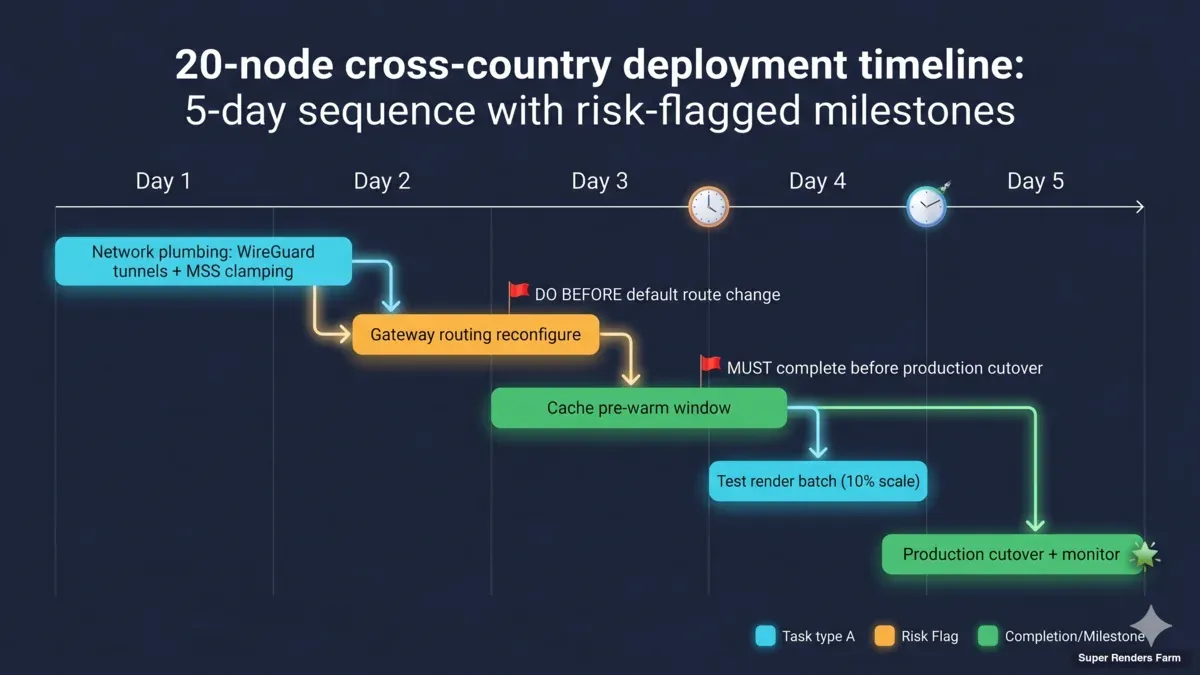
Deployment timeline Gantt chart showing 20-node cross-country render farm sequence with risk flags pre-warm window MSS clamping and gateway routing milestones
These are five operational lessons that, on every dedicated cluster we have stood up, have either saved us hours of debugging or — when we forgot to apply them — cost us hours of debugging.
1. Dual-home gateway routing trap. When the edge box has two network interfaces (one public, one LAN), the order of operations matters. The LAN route must be configured before the default route is changed. If you switch the default route first and then try to add the LAN route, the SSH session you used to log in can drop the moment the default route changes, and you can lock yourself out of the box. The fix is procedural, not technical: always configure internal routes first, validate them, and only then touch the default route.
2. WireGuard and DNS. dnsmasq must explicitly list every interface it should listen on, including the WireGuard interface. If you only list the LAN interface, DNS lookups from VPN clients time out — but ping responses still work, because ping does not go through DNS. This is one of the most diagnostically misleading failure modes we have hit. The fix is one line in the dnsmasq configuration, but you have to know to look for it.
3. TCP MSS clamping is not optional through a tunnel. TLS handshakes, RDP sessions, SMB large-file reads — anything that wants to send large packets — will drop silently if MSS is not clamped. The first symptom is usually "Moonlight works for ten seconds, then freezes" or "SMB lists directories but cannot read files larger than 1 MB." The fix is one iptables rule on the WireGuard host. Apply it before the cluster is handed over.
4. Right-size storage, do not over-engineer. The earlier version of this architecture specified RAID 10 with LUKS encryption on XFS. The cache hardware we deployed was a single SSD. We removed the RAID layer, removed the LUKS layer, and used ext4 — because the cache is not the source of truth, the cloud platform is. Trading paper redundancy at the cache layer for actual redundancy at the cloud layer was the right call. The lesson is to design storage around what the data actually requires, not around what feels safe in a plan document.
5. Pre-warm the cache. On D-Day, every cache miss costs the international link and the cloud platform a round trip. The first hour of production on a cold cache feels slow even when everything else is configured correctly. We now plan a pre-warm window into every engagement — usually one or two days before production starts. The artist does not see the pre-warm; they see a cluster that already feels fast on the first frame.
These are operational lessons, not architectural ones. They live in the deployment checklist, not the architecture document. But they separate a cluster that works in theory from one that holds up under real production load. Smaller patterns get applied on a per-engagement basis — the five above are the ones that have shown up on every deployment.
Conclusion
A dedicated 20-node cross-country GPU render farm is the right architecture when IP control is contractual, the engagement is multi-month, the workflow needs custom configuration, and bring-your-own-cloud authentication is non-negotiable. Outside those conditions, a managed render farm is almost always the better answer — the architectural complexity here does not justify itself for project-based work or for teams without a dedicated operations function.
When the conditions do apply, the patterns covered here — Model B credentials, shared cache on ext4, WireGuard hub-and-spoke transport, BBR with MSS clamping, Moonlight + Sunshine for remote desktop, two-tier firewalling — are what we deploy by default. They are not the only valid patterns, but they are the ones that have held up across deployments.
The team behind Super Renders Farm operates both managed render farm rental and dedicated cluster deployments — including the dedicated GPU cluster configurations and cross-country topologies described throughout this guide.
FAQ
Q: How long does a typical 20-node dedicated cluster deployment take? A: Depending on scope, hardware readiness at the facility, and the customer's cloud file-streaming setup, a typical engagement takes from a few weeks of lead time for hardware and network provisioning, through a pre-warm window of one to two days before production starts. We size the timeline against the customer's production calendar rather than against a fixed template.
Q: What if my team is split across three continents? A: The WireGuard hub-and-spoke topology scales to additional client locations without changing the cluster architecture. Each remote artist runs a WireGuard client and connects to the same hub at the cluster facility. Latency from each region is determined by the public-internet path between that region and the hub; in our experience BBR and MSS clamping make the difference between usable and unusable on those paths.
Q: Can I see the cluster from my end before committing to a multi-month engagement? A: We typically arrange a proof-of-concept window during the scoping conversation. The exact form depends on the customer's project — sometimes it is a single node remote-desktop session to test the artist experience, sometimes it is a small-scale render test to validate the cache and cloud file-streaming integration. Specific terms are a business discussion; reach out to our sales team to talk through what would work for your timeline.
Q: How is data security handled at end of engagement? A: Because Model B keeps customer credentials out of our hands, end-of-engagement closure focuses on hardware and cache cleanup. We wipe the SMB cache, reimage every node from the clean baseline, and provide a written attestation that the cache and node images have been destroyed. The customer revokes their own cloud file-streaming sessions, which is outside our system. Specific contractual language (NDA, SLA, attestation letter wording) is handled by our sales team.
Q: What if I need more than 20 nodes? A: The 20-node configuration is the most common shape we deploy, but the architecture scales beyond that. Larger fleets are added within the same facility — additional reserved nodes feed into the same WireGuard hub, the same SMB3 cache, and the same uniform Windows image. The practical limit is usually cache bandwidth: a single edge-and-cache box has a finite SMB read ceiling, and at very large fleet sizes the cache architecture itself needs to be re-thought (multiple cache boxes, regional caches). We talk through these design choices on a per-engagement basis.
Q: Can I bring my own license for Cinema 4D, Redshift, or other DCC tools? A: License model — bring-your-own-license versus provider-supplied — is a business decision that depends on the specific DCC and the customer's existing license inventory. Some configurations work cleanly with customer licenses; others are simpler with provider-supplied. We work this out during the scoping conversation. Reach out to our sales team for specifics.
Q: How do you handle cloud storage from EU versus US providers? A: The cloud file-streaming platform is the customer's choice. Our cluster integrates with any platform that can run a sign-in client on Windows and expose the customer's project tree as a mounted filesystem. The geographic location of the upstream cloud affects the international latency of the customer-to-cluster path — which is why we recommend the WireGuard hub-and-spoke transport and the BBR-tuned configuration for cross-country setups. We do not host the cloud platform itself; that remains under the customer's account.
Q: What happens if the WireGuard tunnel drops? A: WireGuard automatically re-establishes the session when the underlying network recovers; the customer's remote-desktop session may pause briefly during the re-handshake. If the tunnel drops while a render is in progress, the render itself continues running on the node (it is not dependent on the tunnel for in-progress work), but write-back to the cloud will queue until the tunnel is restored. We monitor tunnel health from the edge box and alert on extended downtime.
About Thierry Marc
3D Rendering Expert with over 10 years of experience in the industry. Specialized in Maya, Arnold, and high-end technical workflows for film and advertising.